

 Global Finds
  Quick Commerce
  Daily Bazar
  Electronics & Appliances
  Mother, Baby & Toys
  Beauty
  Sports
  Automotive
  Stationery, Books & Music
 _20.png) Fashion Luxe
Fashion Luxe  Jersey
  Sports Shoes
  Fashion
 _20.jpeg) Home
Home  Garden & Pet Care
  Special Weekly Offer
  Grocery
  Global Finds
  Quick Commerce
  Daily Bazar
  Electronics & Appliances
  Mother, Baby & Toys
  Beauty
  Sports
  Automotive
  Stationery, Books & Music
 _20.png) Fashion Luxe
Fashion Luxe  Jersey
  Sports Shoes
  Fashion
 _20.jpeg) Home
Home  Garden & Pet Care
  Special Weekly Offer
  Grocery

Description: HT12D HT-12D Decoder Remote Control IC Chip For RF Remote Control Systems DIP-18 Pin IC
HT12D HT-12D Decoder Remote Control IC Chip For RF Remote Control Systems DIP-18 Pin IC
Specification:
- Operating voltage: 2.4V~12V
- Input Voltage: VSS-0.3 to VDD+0.3V
- Storage Temperature:50°C to 125°C
- Operating Temperature :20C to 75C
Features:
- 12-bit Decoder IC to be used with HT12E
- Decoded data has 4 Data bits and 8 Address bits (8+4=12-bits)
- Commonly used for RF and IR wireless transmission
- Operating Voltage 5V
- Low stand by current of 0.1uA at Vcc=5V
- Available in 16-pin DIP, 20-pin SOP
Where to use HT12D RF Decoder
TheIC HT12Dcan be used only with its pairHT12E. These two ICs together form anEncoder and Decoder pair. They are 12-bit Encoders/Decoders, meaning they can transmit 12-bit a data among them. But your encoder IC should not communicate with someone else’s decoder IC, so an Encoder and Decoder IC pair will share a common Address which is an 8-bit data. So out of the 12-bits 8-bits will be used to set address and the remaining 4-bit will be used to transmit data. With 4-bit data we can create 16 types (2^4 =16) of combinations. These IC’s are commonly used with RF pairs or IR pairs. So if you are working on a project which has to transmit a 4-bit data from one end to other either by wire or wireless then this IC pair will be best suited for you.
How to use a HT12D RF Decoder
The primary function ofHT12Dis to decode the 12-bit that is received by the input pin. Since the IC comes with an in-built Oscillator it is very easy to make this IC work. The IC is should be powered by 5V (pin 18) and the ground pin (pin 9) is grounded. For decoding a data the IC will requires anoscillator, luckily this IC has one in-built. We just have to connect the OSC1 and OSC2 (pin 15 & 16) through a 470K resistor to invoke it. The 4-bit data that is received can be obtained on pins AD0 to AD1 and an address of 8-bit has to be set using the pins A0 to A7. It is very important that your Decoder should have the same address of that of the encoder. A basiccircuit diagram for the HT12D ICis shown below
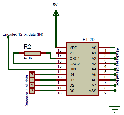
In the above circuit I have set the 8-bit address data as 0b00000000, by connecting all address pins to ground. If you want security you can connect any of the 8 pins to 5V to make it high. The complete IC is powered by a +5V supply which could be obtained from a voltage regulator like7805.The pins AD3, AD2, AD1 and AD0 are connected to any Digital IC that can read the 4-bit data. They can also be connected to LED to physically view the received data. In this the 4-bit output data is just shown as “?” since we do not know what the Encoder IC has sent to the Input pin. If any valid data is received they can be obtained from these four pins.
To know how a 4-bit data can be encoded and then send to the input pin of this IC, we have to understand the working of theHT12E Encoder ICwhich is givenhere.
Applications
- Used to convert Parallel 4-bit data to series data
- Highly useful in wireless communication projects involving RF or IR
- Remote controlled systems like garage doors, Car alarm system, Car door controls etc.
- Can be used in Home automation for short range remote switching
- Safety systems like Burglar alarm system, Smoke or Fire alarm system etc..
- 12-bit Decoder IC to be used with HT12E
- Decoded data has 4 Data bits and 8 Address bits (8+4=12-bits)
- Commonly used for RF and IR wireless transmission
- Operating Voltage 5V
- Low stand by current of 0.1uA at Vcc=5V
- Available in 16-pin DIP, 20-pin SOP

Login to ask a question
