

 Global Finds
  Quick Commerce
  Daily Bazar
  Electronics & Appliances
  Mother, Baby & Toys
  Beauty
  Sports
  Automotive
  Stationery, Books & Music
 _20.png) Fashion Luxe
Fashion Luxe  Fashion
 _20.jpeg) Home
Home  Garden & Pet Care
  Special Weekly Offer
  Grocery
  Global Finds
  Quick Commerce
  Daily Bazar
  Electronics & Appliances
  Mother, Baby & Toys
  Beauty
  Sports
  Automotive
  Stationery, Books & Music
 _20.png) Fashion Luxe
Fashion Luxe  Fashion
 _20.jpeg) Home
Home  Garden & Pet Care
  Special Weekly Offer
  Grocery

Description: Metal Detector Module Contactless Induction
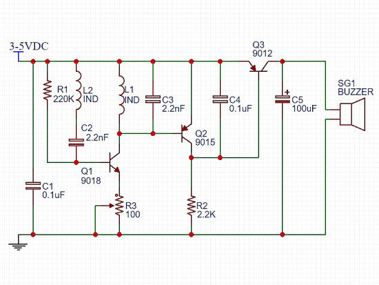
The cheap module I received from China had no instruction manual or circuit diagram, so I had to do a lengthy Google search in order to get its basic schematic. In this concise primer you will have the schematic and all other details you need to know if you want to make a simple metal detector on your own. So, let’s start!
The clever part of the design is the single rectangular coil made by etching one continuous track on the printed circuit board. If you look very carefully at the printed circuit board, you can see that the rectangular coil is tapped at one turn i.e. a single coil with a precise tapping at one turn. The coil starts at the top side of the double-sided printed circuit board and makes square loops towards the center, A via in the center of the printed circuit board takes the coil to the other side of the printed circuit board and the same set of tracks are on the bottom side. Pretty nice!
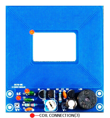
A handful of commonly available discrete components remain including three bipolar junction transistors, a few resistors, and capacitors. The sounder in the module is a standard active piezo-buzzer, and there’s also a small trimpot to fine-tune the circuit. Here is the basic schematic of the metal detector module. I borrowed it from the seller’s webpage.
Features:
- Working voltage: 5V DC.
- Detector distance: 1CM.
- Dimensions: 66 x 60 x 14 (LxWxH) mm.
- Weight: 15 gm.
- Redline: connect to power positive
- Black line: connect to power negative
- Adjust the potentiometer, let the modules work normally.
Metal Detector Module Contactless Induction
Features:
- Working voltage: 5V DC.
- Detector distance: 1CM.
- Dimensions: 66 x 60 x 14 (LxWxH) mm.
- Weight: 15 gm.
- Redline: connect to power positive
- Black line: connect to power negative
- Adjust the potentiometer, let the modules work normally.
- Play equipment development
- Metal proximity switch
- Metal detection in human body

Login to ask a question
